Topic: DMD0351

Process Control Basics
There are many analog control strategies available for industrial processes, and the best one to choose depends on the particular application. The two most common types of analog control used in the industrial control world are open loop control - sometimes referred to as an ON-OFF control, and closed loop control - normally referred to as PID control.
Open Loop Example - Thermostat
A good example of a common ON-OFF control application is located in your house, the thermostat which is used to control the heat and air conditioning system. To make the temperature of the house comfortable, the thermostat is set to the desired temperature (the setpoint). Then the “comfort” mode is set to either heating or cooling. A temperature sensing device is located within the thermostat to provide the required analog input value to monitor (the process variable.
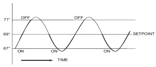
If the thermostat is set for heating, and the setpoint is set to 69°, the furnace will turn on to provide heat at, normally 2° below the setpoint. In this case, it would turn on at 67°. When the temperature reaches 71°, 2° above setpoint, the furnace will turn off.
If the thermostat is set for cooling, and the setpoint is set to 76°, the A/C unit will turn on when the sensed temperature reaches 2° above the setpoint or 78°, and turn off when the temperature reaches 74°, 2° below the setpoint.
This type of control is called ON-OFF controller because the output is either fully ON or fully OFF. The waveform below shows the action of the heating cycle. Note that there is a slight overshoot at the turn-off point and a slight undershoot at the turn-on point.
Why use Closed Loop Control?
Although the Open Loop (ON-OFF) controller is used in some industrial control applications, is not practical in the majority of industrial control processes. The most common process controller that is used in the industrial world is the Closed Loop (PID) controller.
The Closed Loop controller monitors a continuous feedback loop that keeps the process output (control variable) within an acceptable range by taking corrective action whenever there is a deviation from the desired value (setpoint) of the process variable (PV) such as, rate of flow, temperature, voltage, etc. An “error” occurs any time the setpoint deviates from the process variable. “Errors” are caused by events such as an operator manually changing the setpoint, or a disturbance changing the load, etc.. The PID controller receives signals from the input sensors and computes the corrective action to take. This computation is based on the size of the error (Proportional), the sum of all previous errors (Integral) and the rate of change of the error (Derivative).
Closed Loop Example – Cruise Control
The cruise control on an automobile is a good example of a simple PID control system. The driver engages the cruise control by turning it ON, and then manually brings the car to the desired cruising speed, for example, 70 miles per hour. Once the cruise speed is reached, the SET button is pushed fixing the speed at 70 mph, this becomes the setpoint. On flat terrain the automobile will cruise at a steady 70 mph and the cruise control system will take no corrective action because there is no “error” (SP – PV = 0).
When the automobile comes to a hill it will slow down as it climbs up the hill. The speed sensor in the wheels senses this slow down – an “error” is generated (SP – PV > 0) – and causes the throttle to increase the fuel to the engine. The automobile accelerates in an effort to maintain 70 mph. As the automobile is accelerating the “error” value is decreasing so the PID controller signals the throttle to use less fuel. This process smoothly accelerates the automobile back to the setpoint.
When the terrain levels out after reaching the top of the hill the automobile will speed up. The speed sensor senses too much speed (SP – PV < 0) and signals the throttle to provide less fuel to the engine, thus, the engine slows down allowing the automobile to maintain the 70 mph speed.
Whereas the output value of the Open Loop controller is always fully on or fully off, the output value of a closed loop controller is proportional to the difference between the setpoint (SP) and the process variable (PV).
Process Control Definitions
Here is a list of the terms and their definitions that are used in the following discussion of Closed Loop Control systems:
Proportional - is commonly referred to as Proportional Gain, or just Gain. The proportional term is a corrective action which is proportional to the error, that is, the change of the manipulated variable is equal to the proportional gain multiplied by the error (the activating signal). In mathematical terms:
Proportional action = Proportional Gain (P) * Error
Integral - this term is often referred to as Reset action. It provides additional compensation to the control output, which causes a change in proportion to the value of the error over a period of time. In other words, the reset term is the integral sum of the error values over a period of time.
Derivative - this term is often referred to as Rate. The Rate action adds compensation to the control output, which causes a change in proportion to the rate of change of error. Its job is to anticipate the probable growth of the error and generate a contribution to the output in advance.
Manufacturing Process – refers to the set of actions that adds value to raw materials. The process can involve physical changes and/or chemical changes to the material. The changes render the material more useful for a particular purpose, ultimately used in a final product.
Process Variable – refers to the controlled variable part of the process that you wish to control. It may be temperature, pressure, level, flow, composition, density, the ratio of two streams, etc.
Setpoint – is the target value for the process variable. When all conditions of the process are correct, the process variable will equal the setpoint.
Control Output – is the result of the loop calculation, which becomes a command for the process (such as the heater level in an oven). This is sometimes referred to as control variable.
Error Term – is the algebraic difference between the process variable and the setpoint. This is the control loop error, and is equal to zero when the process variable is equal to the setpoint (desired) value. A well-behaved control loop is able to maintain a small error term magnitude.
Manipulated Variable – is what is used to affect the controlled variable. For example, the flow rate of the fuel used in a furnace might be manipulated in order to control the temperature.
Disturbance – refers to anything in the system that changes so that some corrective action is required. For instance, when controlling a flow and the upstream pressure drops, the control valve must open wider in order to keep flow constant. The drop in upstream pressure is the disturbance.
Final Control Element – refers to the physical device used to control the manipulated variable. Valves are a good example of devices that are used as the final control element.
Lag Time – is the amount of time it takes for the process to respond to a change in manipulated variable. This is also known as the capacitance of the system. When you’re in the shower and you turn up the hot water a little, the time it takes before the water gets hotter is the lag time.
Dead Time – refers to the amount of time it takes for a change in the process to be recognized. Composition analyzers and quality control are usually sources of significant dead time.
Loop Configuring – also known as Loop Tuning refers to the operator-initiated selections which set up and optimize the performance of a control loop. The loop calculation function uses these configuration parameters in real time to adjust gains, offsets, etc.
Loop Monitoring – The function which allows an operator to observe the status and performance of a control loop. This is used in conjunction with the loop configuring to optimize the performance of a loop (minimize the error term).
See Also:
Process Control Basics
Process Control Instruction Set
Using the PID Process Simulator
Related Topics:
PID Calculation and Tuning Constants
PIDINIT - Set PID Tuning Constants
Alarm Handlers
Input and Output Value Limiters
DEADBAND - Set Outside Deadband
Noise Suppression
INTEGRAT - Integrate Over Time
Ramp/Soak Profiles - up to 250 steps per Profile
Input and Output Scaling
Analog Control using a Discrete Output
TIMEPROP - Time Proportional Control